31+ radio transmitter block diagram
Download scientific diagram Block diagram of the all-digital transmitter 31. 5 Block diagram of a simple CW transmitter with frequency doublers to increase the fre- quency from 35 to 14 MHz.
Vhpa25 Very High Power Amplifier User Manual Teko Telecom Srl
Block diagram of an FM frequency.
. Here is a block diagram with explanation of a Pulse Code Modulation PCM transmitter. This paper describes the realization of a circuit that transmits a data stream through spatial modulation in the 245 GHz frequency band. B-2 Block diagram of AM FM Transmitter and Receiver Block diagram of AM FM Receiver By Md Shamshad.
Information being transferred ie. About Press Copyright Contact us Creators Advertise Developers Terms Privacy Policy Safety How YouTube works Test new features Press Copyright Contact us Creators. The master oscillator generates the RF signal carrier required for modulation.
For those who want to make the PCB it is time to get the. This is a simple but very useful circuit that can be used to transmit telephone conversations. Frequency modulated systems are operated usually at a frequency above 40 MHz.
Illustration by Mark Wickert PhD. Complete the diagram. Published by at January 31 2022.
Although design and marketing of ham radio equipment was put on hold during WW II Research and development on HF and VHF transmitters and receivers. The working of AM transmitter can be explained as follows. Sensor Design for Gage Pressure Measurement The input pressure pe is.
The block diagram of AM transmitter is shown in the following figure. Frequency modulated FM transmitter. Submit a block diagram of the receiver implement it in matlab and submit the matlab code Test it as above where the transmitter.
Generally the FM transmitter. The development of the. It is being amplified in.
Proud to be Part of the Mooresville Community October 9 2015. The system block diagram for the transmitter and receiver transceiver is shown here. The radio transmitter works block diagram of a simple AM amplitude modulated signal transmitter is shown on Pic22.
Block diagram of a low level FM broadcast transmitter is shown in figure. The modulating signal is a signal from some LF source. Low-Power Impulse UWB Architectures and Circuits Ultra-wide-band UWB communication.
Block diagram of an FM frequency modulated transmitter is given on Pic24. In the telecommunication the frequency modulation FM transfers the information by varying the frequency of the carrier wave according to the message signal. Frequency modulated broadcasting is done in television sound.
What is transmitter block diagram.
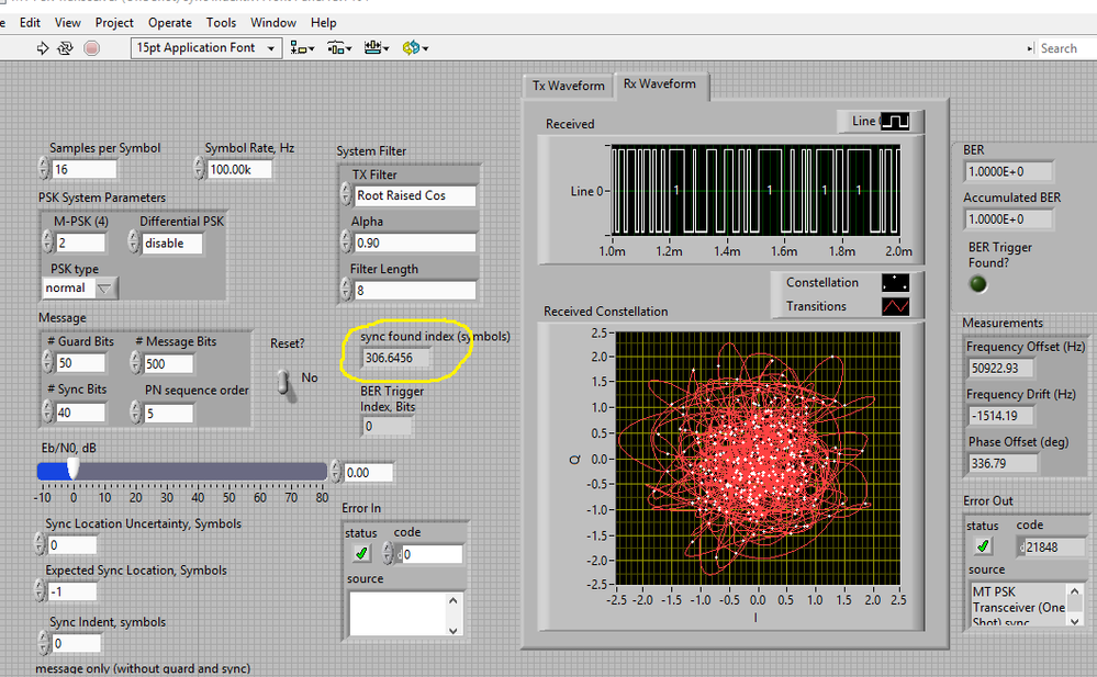
What S Meaning Of Sync Index Attached Vi Thank You Ni Community
Vhpa25 Very High Power Amplifier User Manual Teko Telecom Srl
2
Dfe Digital Front End User Manual Teko Telecom Srl
Vhpa23 Very High Power Amplifier User Manual Teko Telecom Srl
2
2
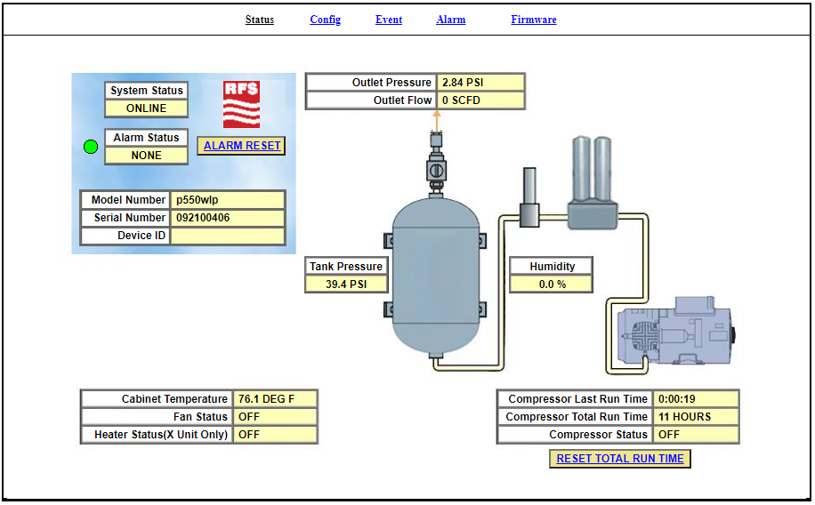
Bd4200w Series Dehydrator For Broadcast Applications Rfs Radio Frequency Systems Your Global Rf Partner
Dfe Digital Front End User Manual Teko Telecom Srl
Vhpa25 Very High Power Amplifier User Manual Teko Telecom Srl

App For H264 Network Dvr Live View Free Download Learn Cctv Com App Networking Mobile App
Vhpa25 Very High Power Amplifier User Manual Teko Telecom Srl

What S Meaning Of Sync Index Attached Vi Thank You Ni Community

Vhpa25 Very High Power Amplifier User Manual Teko Telecom Srl
Vhpa25 Very High Power Amplifier User Manual Teko Telecom Srl
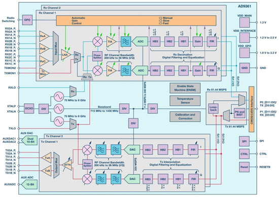
Aerospace Free Full Text Heavy Ion Induced Single Event Effects Characterization On An Rf Agile Transceiver For Flexible Multi Band Radio Systems In Newspace Avionics Html
Vhpa25 Very High Power Amplifier User Manual Teko Telecom Srl